Introduction
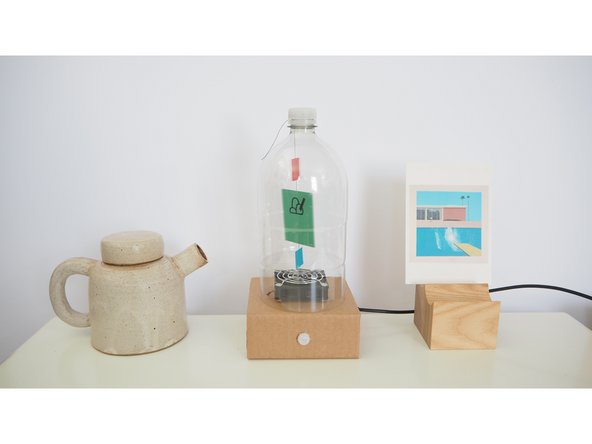
Flutter By Thaumatrope spins a card with different parts of the same picture on opposite sides, causing them to appear superimposed on one another when activated.
Build Flutter By Thaumatrope with a few simple materials; a plastic bottle, some corrugated cardboard and coloured paper. Make your own drawing for the Thaumatrope or print our PDF to use the one featured in this guide.
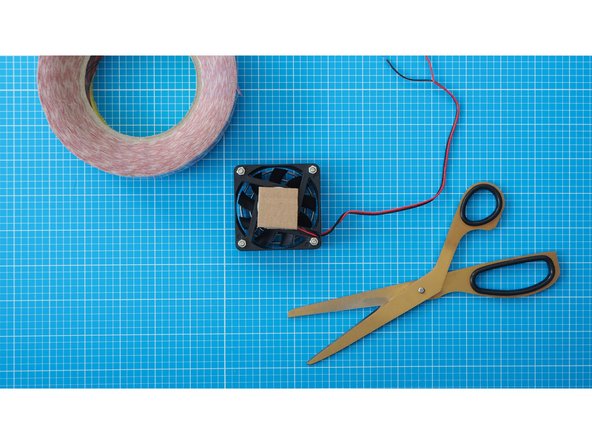
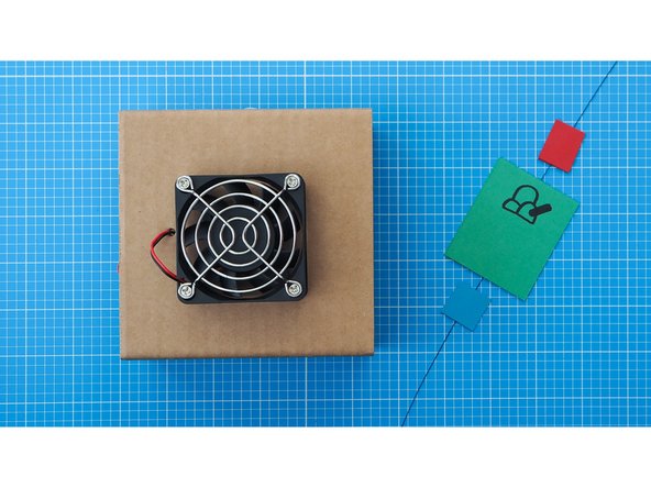
Please Note: This enclosure design uses the 60cm computer fan rather than the mini computer fan.
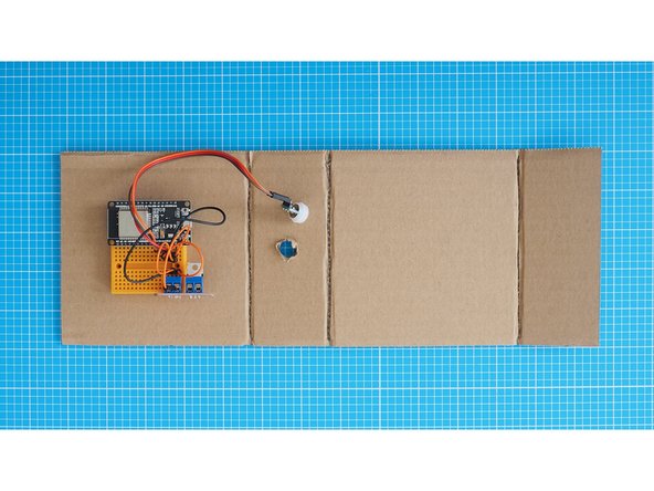
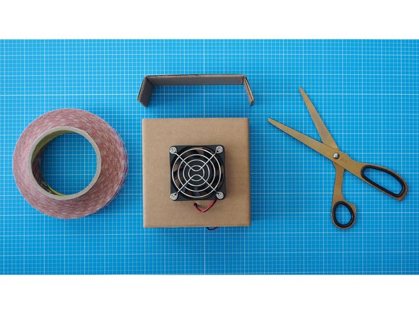
To begin this step you’ll need to have your Flutter By breadboard assembly already made (one or two of them depending on whether you are intending to pair them yourself, or pair remotely). You’ll also need to have ready the necessary tools and parts which can be sourced from a range of independent online retailers - click the parts links for more details including tailored options for certain countries.
-
-
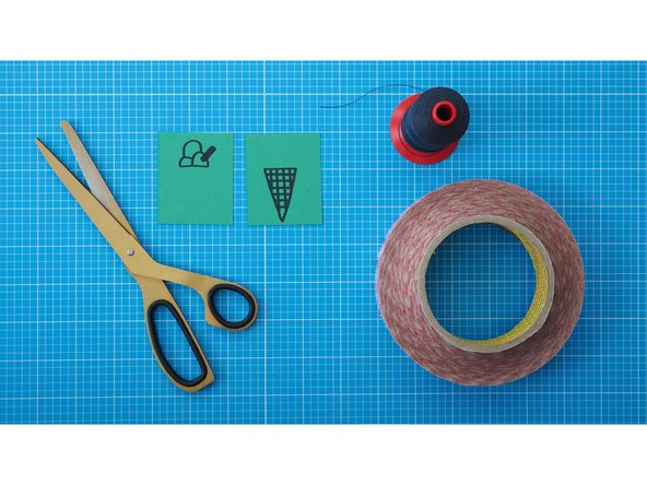
Gather the items from the parts and tools lists
-
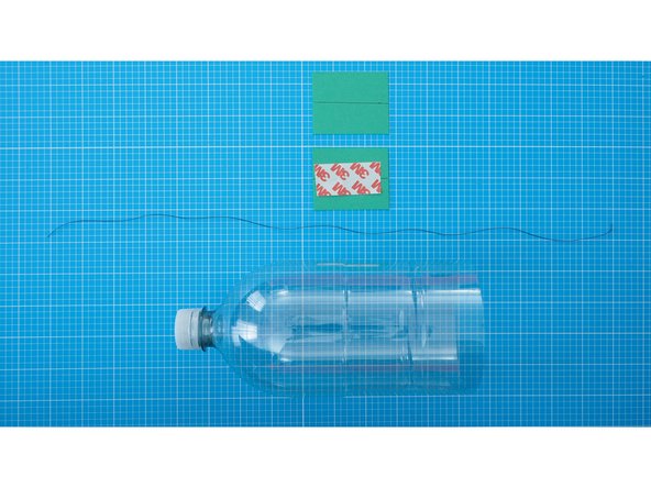
You can draw your own pictures for the Thaumatrope, or you can use the ones with provide in the Flutter By Thaumatrope drawings PDF.
-
-
-
If your 60mm is pre-fitted with a plug at the end of the lead, it can be connected to the same male to male jumpers that the small fan was connected to during the breadboard assembly.
-
If your fan didn't have a plug, the exposed wires of the lead can be screwed directly into the MOSFET terminals.
-
The rest of this guide features a fan without a plug.
-
You can remove the plug and trim the leads if would prefer to connect the fan directly to the MOSFET.
-
-
-
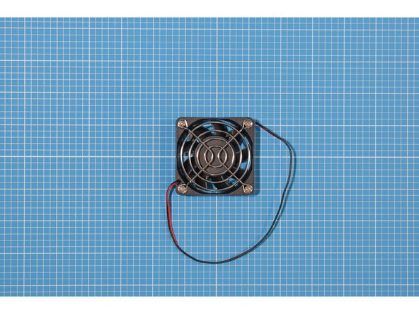
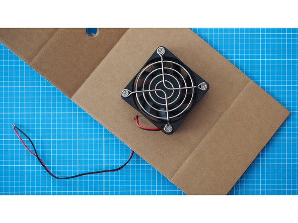
The fan will have been supplied with a metal grill, nuts and bolts.
-
Place the grill on top of the fan, opposite to the side that has a label. The grill will be covering the finned hub that rotates.
-
Insert the bolts through the grill and fan.
-
Add the nuts to the ends to the bolts to fasten the grill in place.
-
-
-
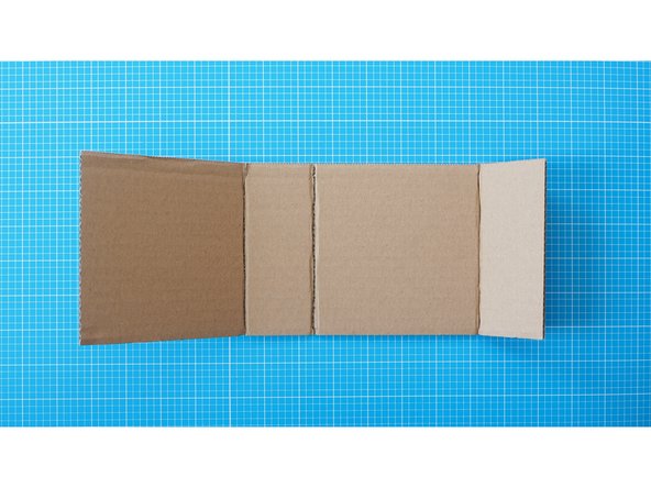
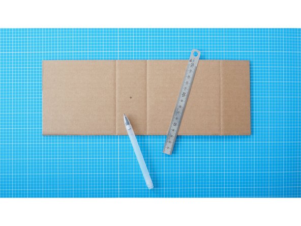
Cut a 12cm x 34cm rectangle of cardboard with a pair of scissors.
-
Score gently through only the top layer of the cardboard to create crease lines. The fold lines should be made according to the guide; at 12cm, 17cm and 29cm mark.
-
Now fold the cardboard along the three crease lines.
-
-
-
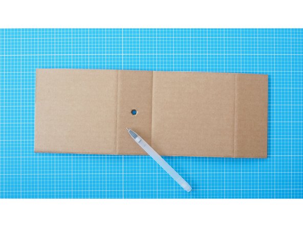
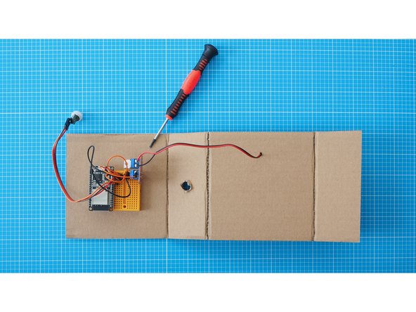
Turn the cardboard around and mark the middle of the 2nd segment as shown in the photograph.
-
Using a bradawl or other sharp point, carefully make a hole in the centre of the mark.
-
Gently enlarge the hole using a pencil.
-
Gently enlarge the hole again using a marker pen such as a Sharpie until it matches the diameter of the PIR sensor.
-
Take care to make the hole no wider than the PIR sensor itself.
-
You can also use a craft knife to create the hole if you have access to one.
-
-
-
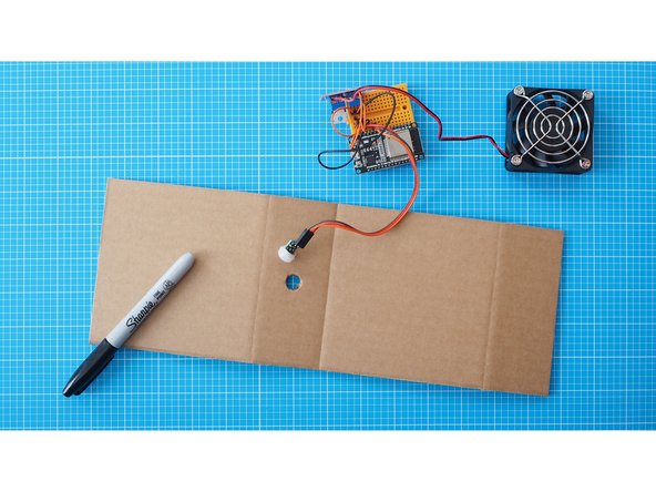
Make sure the white cap of the PIR fits through the hole
-
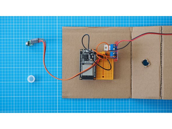
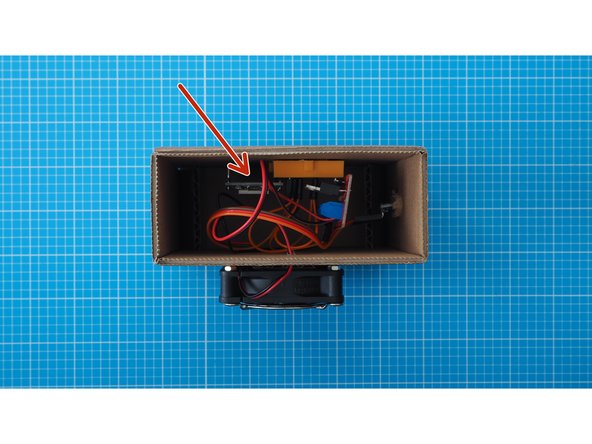
Temporarily unscrew the fan from the MOSFET module.
-
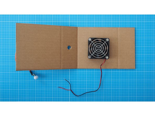
Mount the breadboard assembly onto the 1st segment of the cardboard as shown here. The breadboard has a double-sided tape backing which can be used to attach it.
-
Make sure the cardboard faces with the crease lines up. You will fold the structure around the breadboard in the next steps.
-
-
-
Cut and attach a small piece of cardboard onto the bottom of the fan, secured with a piece of double sided tape.
-
Add another piece of double sided tape to the top of the cardboard.
-
-
-
Use the double sided tape to stick the fan to the backside of the 3rd cardboard segment using the tape. Make sure the fan is centered and that the scored lines of the cardboard are facing down as shown here.
-
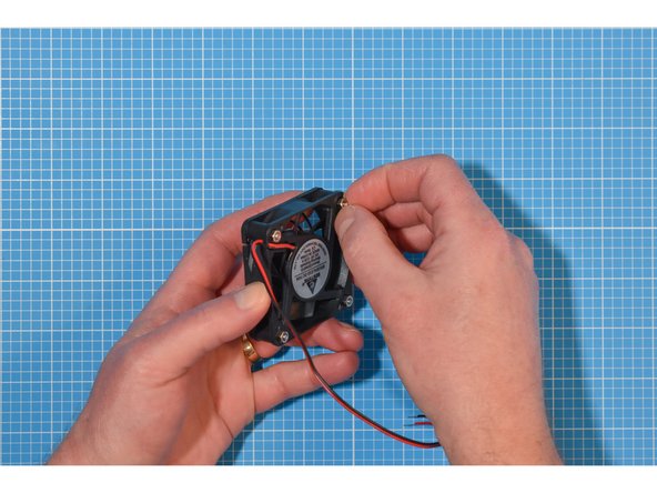
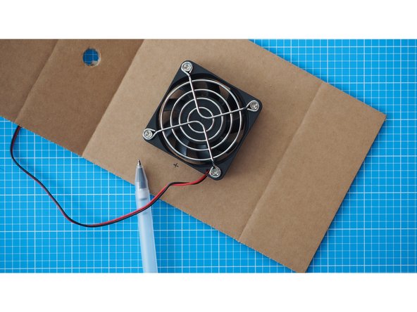
Make a small mark on the side of the fan where the cable is attached.
-
Make a small hole where you've made the mark using a bradawl or other sharp point.
-
Thread the cable through the cardboard.
-
-
-
Now reattach the fan leads back into the MOSFET module.
-
Remove the white plastic cap from the PIR sensor.
-
Fit the cap through the large hole you made in the second section earlier, from the front.
-
From inside the container, fit the PIR sensor back into the plastic cap to hold the PIR in place on the enclosure.
-
-
-
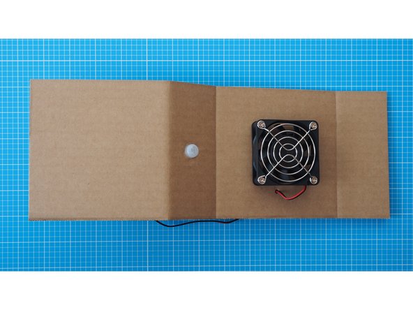
Fold the cardboard around into a rectangle and secure by sellotaping the edge shut.
-
-
-
Cut another piece of cardboard to fit within the side of the box. It should be 5cm x 12cm with some extra length at either side to make flaps.
-
Fold the sides of the cardboard.
-
-
-
Fix the cardboard piece into the side of the enclosure. Use the side that is further from the MOSFET module and usb cable connector.
-
You can leave the other side of the cardboard enclosure open for easy access.
-
Make sure the open side gives access to the power socket on the ESP32s board
-
-
-
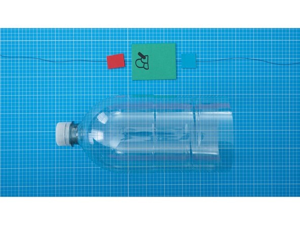
Cut the bottom from of a plastic bottle carefully with scissors and discard.
-
Make sure the bottom is cut evenly, so that the bottle stands straight.
-
The upper part of the bottle should be at least 20cm long.
-
-
-
Now make the drawing for the Thaumatrope. Either use our PDF template or draw your own onto coloured paper - 6cm wide by 5cm high .
-
Each side should have one part of the drawing.
-
Thick bold illustration lines work best to see the effect whilst spinning.
-
-
-
Make a vertical line on the rear of each drawing to divide the paper in two.
-
Cut and align the thread along the line, then use double-sided tape (or a glue stick) to bond the paper and thread together.
-
You can attach smaller pieces of coloured paper to the top and bottom of the main drawing.
-
-
-
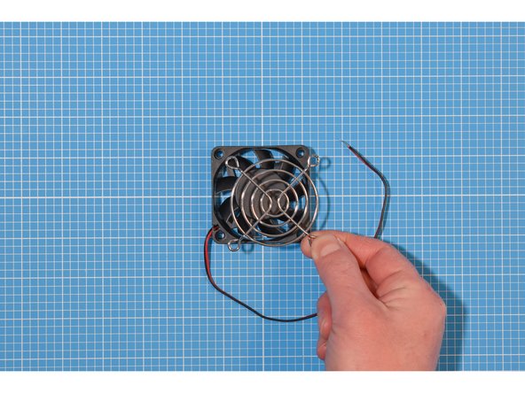
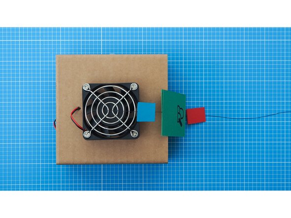
Securely tie the thread of the Thaumatrope to the middle of the fan grill.
-
Trim the thread so that it has the length of the bottle + ca. 10cm.
-
-
-
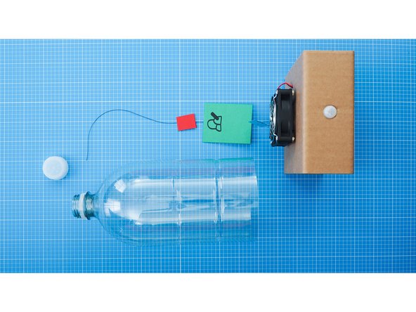
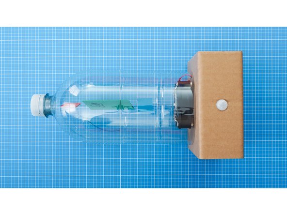
Place the bottle on top of the fan.
-
Pull the thread tightly through the bottle and screw the bottle cap back on.
-
Make sure the thread isn't stretched.
-
-
-
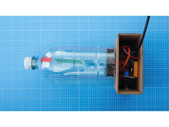
Plug the USB cable into the ESP32s board and power the device.
-
-
-
Once paired with a second device, any movement detected by the PIR sensor on one device will trigger the fan in its partner to turn.
-
If the motion seems slow or laboured, you may need to adjust the centering of the Thaumatrope with the fan. The effect works best when the alignment is slightly off centre.
-
If you want to adjust the timing of the fan motion (by default it will remain on for 10 seconds after the PIR detects motion), please refer to the optional step in stage one of the hardware building guides.
-
-
-
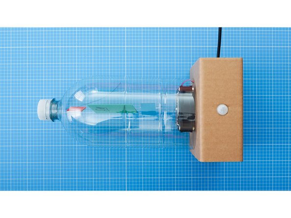
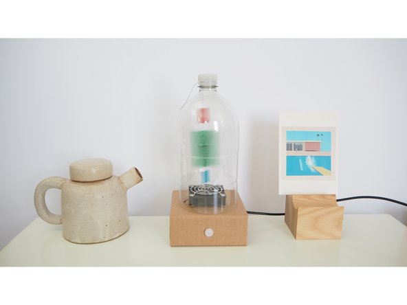
The enclosure is ready to use.
-
Remember you can adapt these instructions to suit your needs.
-
You can also adapt the Thaumatrope drawings however you wish.
-
We would love to see your interpretations! Email us at interaction@gold.ac.uk or tag your social posts with #yoyomachines
-
Enjoy!!
-