Introduction
Build a Light Touch enclosure from 2 paper plates, jumper wires, bulldog clips and a few other household items.
To begin this step you’ll need to have your Light Touch breadboard assembly already made (one or two of them depending on whether you are intending to pair them yourself, or pair remotely). You’ll also need to have ready the necessary tools and parts which can be sourced from a range of independent online retailers - click the parts links for more details including tailored options for certain countries.
-
-
Gather the parts and tools shown in the picture.
-
-
-
Remove the LEDs from the breadboard.
-
Add male to female extension jumper wires to each of the legs of the LEDs and place them in their corresponding position in the breadboard.
-
Make sure you have correctly wired up the LEDs, especially checking that the centre 2 legs of each led are wired correctly to the breadboard.
-
Test the device to check that the circuit is working properly.
-
-
-
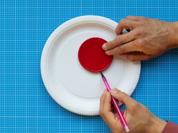
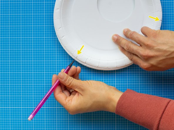
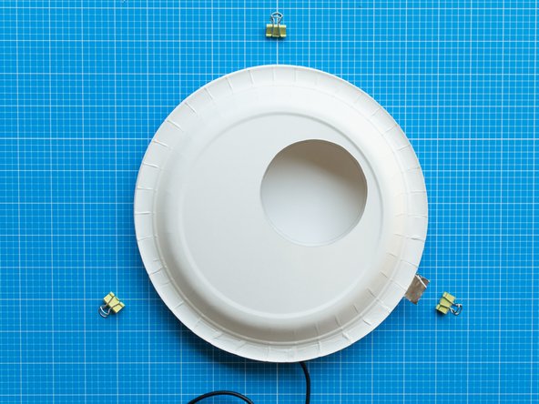
Mark a circular window of approximately 85 mm diameter in one plate. The circle should be located off centre to allow space for storing the electronics.
-
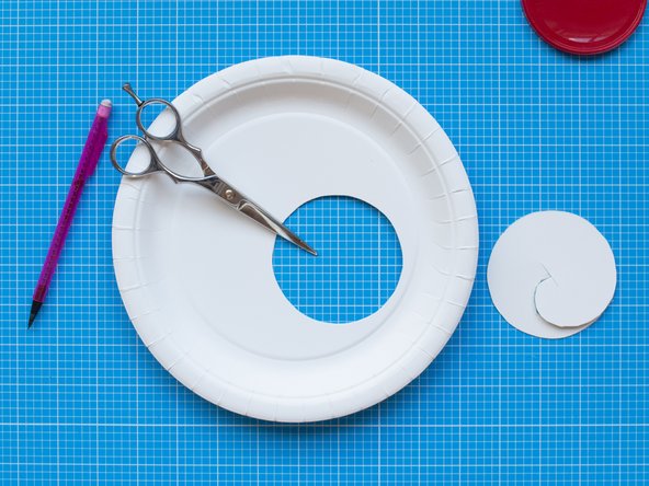
Cut the circle with scissors or a scalpel.
-
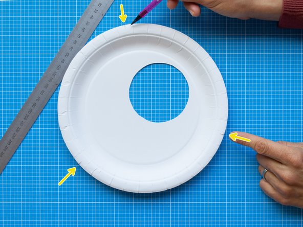
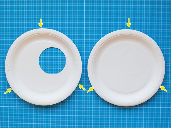
Mark three equidistant points along the edge of the plate. These points will be the guides for positioning the bulldog clips that will hold together the lamp.
-
The backside of the plate will be the front of your light.
-
-
-
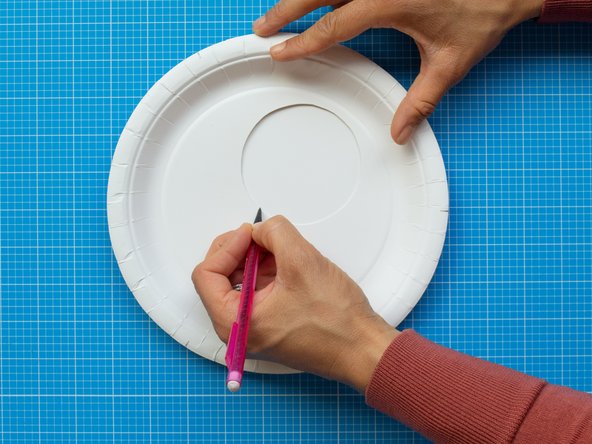
On a new plate, mark the area of the window by placing the cut plate on top. The marked circle will work as a white background for the LED lights of your device. This lighting area should remain clear. All the electronic components will be placed around it.
-
While in position, copy the three marks from the front plate. The marks will help you to align both plates together.
-
-
-
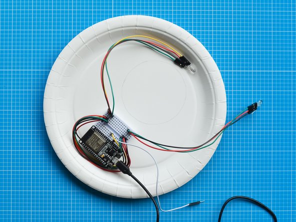
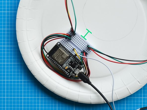
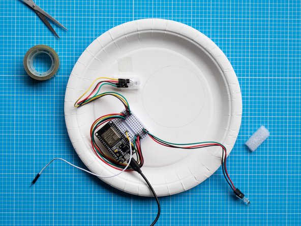
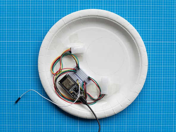
Fix the breadboard assembly around the lighting area as shown in the picture. The breadboard has a double sided tape backing which can be used to attach it to the plate.
-
Position the breadboard at least 1 cm away from the marked area so that it remains hidden once you close the device.
-
Make sure the breadboard cables are tucked under the board. The capacitive touch lead should be left aside.
-
-
-
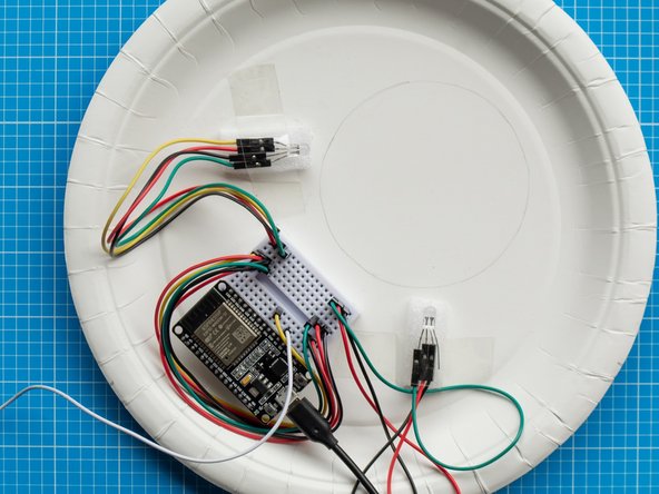
Position the LEDs around the lighting area following the picture as a guide. The LED to the upper left of this image is your 'send' light, the other is your 'receive' light.
-
Once you have decided the right position of both lights, secure the LEDS to the plate with sellotape. Use two foam strips (from ESP32S board packaging) as spacers to elevate the LEDS from the plate.
-
For a better lighting effect avoid having the lights in front of each other.
-
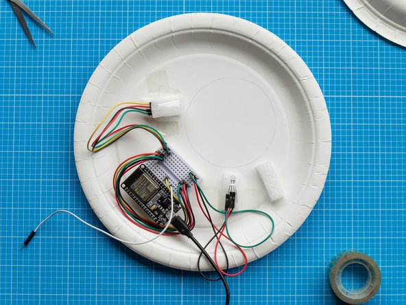
The spacers help to create indirect lighting across the white circular area and their height can change the effect and tones of the light. You can play with the position of the LEDs while having the lights on to get the desired effect.
-
-
-
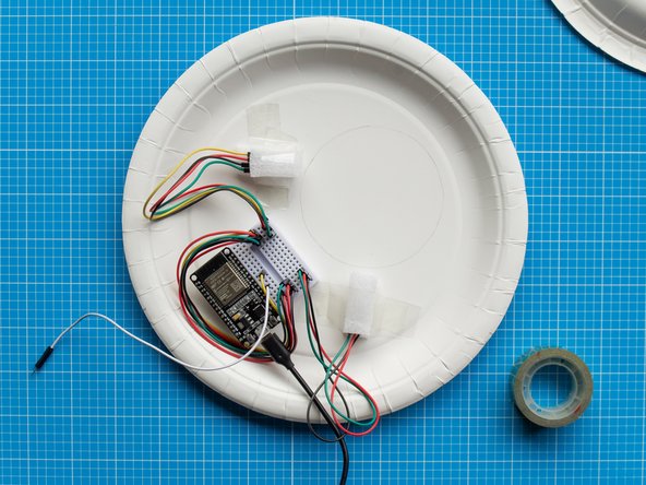
Place the two remainer foam strips on top of each LED and secure them with tape. These will act as a diffuser to the lights.
-
-
-
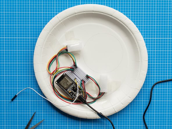
Now that the setup of the LEDs is complete, you can tidy up the cables by securing them to the plate with sellotape. This will help to have a tighter fit when you clip the front and back plate together.
-
Make sure to leave the capacitive touch lead aside.
-
-
-
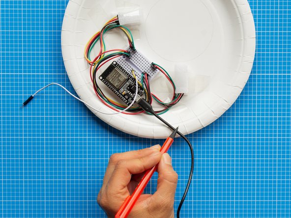
Now you will make an opening on the brim of the plate to let the micro USB lead out so that the front plate and back plate can close together tightly.
-
With a pencil, mark the outline of the USB lead where the cable touches the brim of the plate.
-
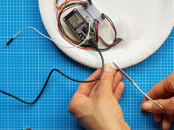
Make an opening in the shape of a slit with the help of scissors. The opening should be slightly wider than the cable.
-
-
-
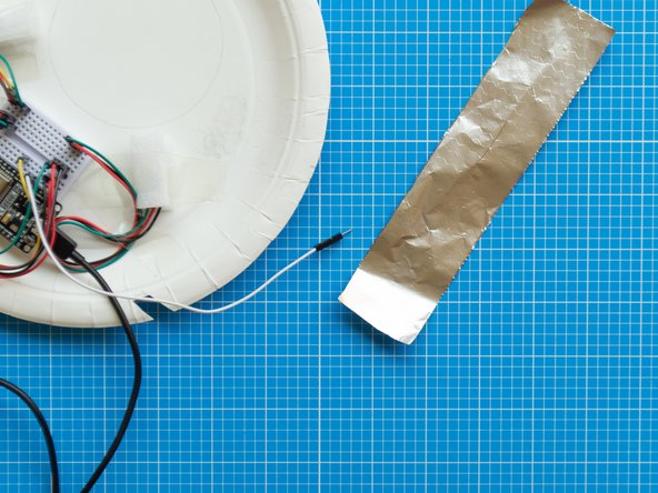
Cut a 4 x 18 cms strip of aluminium foil and fold it in half in both directions until it is about 2 x 9 cms.
-
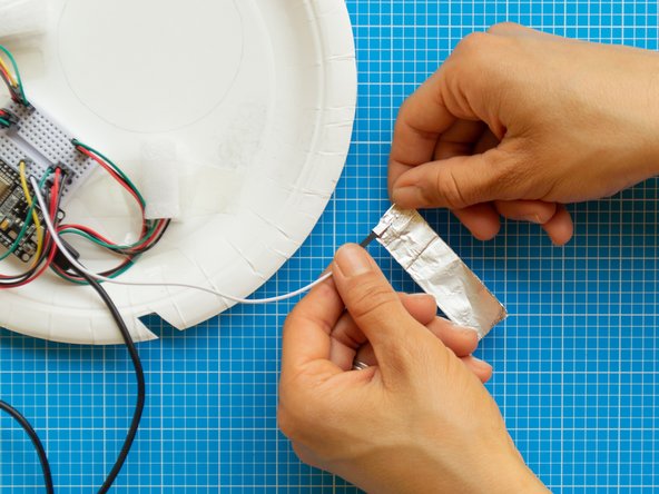
Take one end of the foil strip and wrap it around the pointy connector of the capacitive touch lead.
-
Wrap the connector a couple of times and press it tightly so that it is properly secured to the foil.
-
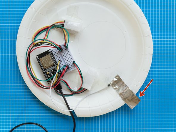
Place the wrapped connector on the plate so that the aluminium foil sticks outside the plate about 1 cm on the right bottom guide mark on the brim of the plate
-
Make sure the sticking foil matches the position of the guide mark as it will eventually be secured with the bulldog clip.
-
Once in position fix the connector and foil strip to the plate with sellotape.
-
-
-
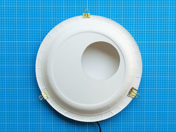
Place the front plate on top of the back plate. The electronics will be fully covered and the white lighting area in the circular window will be clear.
-
Make sure the guide marks in both plates are aligned.
-
Fold back the foil capacitive touch button so that it covers the brim of front plate.
-
Once in position, secure both plates together with the three bulldog clips.
-
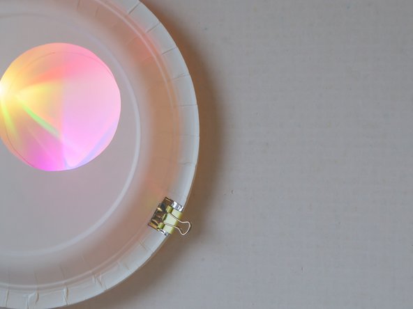
The bulldog clip that touches the foil will become the capacitive touch button, as the foil will transfer a signal whenever the clip is touched.
-
-
-
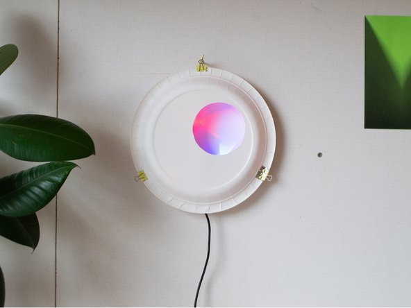
Light Touch is ready to use. You can place it on a wall by hanging it to an eye hook or nail from the top bulldog clip.
-
Choose locations for your device that are not too brightly lit. The LEDs are bright, but may seem washed out if near a sunny window.
-
Light Touch devices work best when plugged into dedicated adaptors like phone chargers. They do not run run well when plugged into laptops or computers as these will struggle to power the LEDs.
-
Enjoy!
-
-
-
Use the capacitive touch bulldog clip to operate the device.
-
Press and hold the bulldog clip to scroll through different colours. Let go to select a colour.
-
Tap quickly on the bulldog clip to send this colour to the your paired Light Touch device.
-
Receive a second colour back from your paired Light Touch device.
-
You can make and pair both Light Touch devices in the same household and post one to your remote partner. Alternatively, they can be made remotely and paired via the internet.
-
Use the Network Setup guide to pair two Light Touch devices. We assume you'll do before you start assembling the electronics, but you can link or re-link them at any time.
-