Tools
-
-
Download the USB driver so the ESP32S board can communicate with your computer. The Mac OS version can be found here.
-
Unzip the download and open the installer SiLabsUSBDriverDisk.dmg.
-
A new window will open. Click on Install CP210x VCP Driver to open the driver.
-
You might be asked for confirmation to open the Driver. To proceed click 'Open'.
-
-
-
Follow the onscreen instructions to install the USB driver.
-
The USB driver will let the ESP32S board communicate with your computer. You don't have to open the driver beyond this step, it will just do its thing in the background.
-
-
-
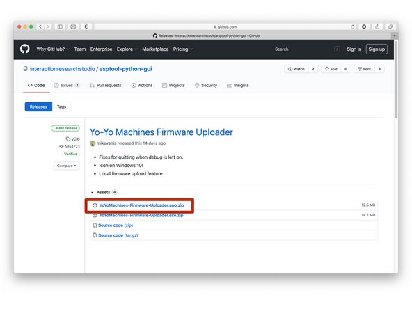
The Yo-Yo Firmware Uploader will enable you to upload the latest firmware to your ESP32S board. Download the latest release here.
-
Firmware is code the ESP32S board needs in order to work as a Yo–Yo device. It's called firmware because it is software used to configure hardware — soft + hard = firm. Geddit?
-
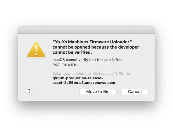
Open the downloaded app. Note that your operating system may ask you to verify the app.
-
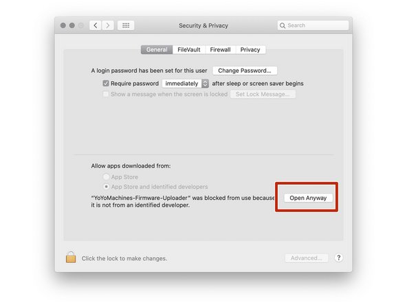
You will need to give permission to open the app in System Preferences > Security & Privacy when prompted.
-
Security & Privacy settings may vary in different versions of MacOS. You can find more information in our FAQs.
-
-
-
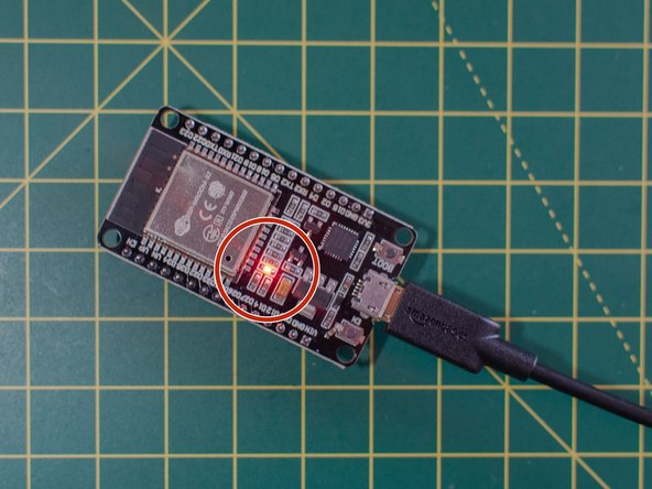
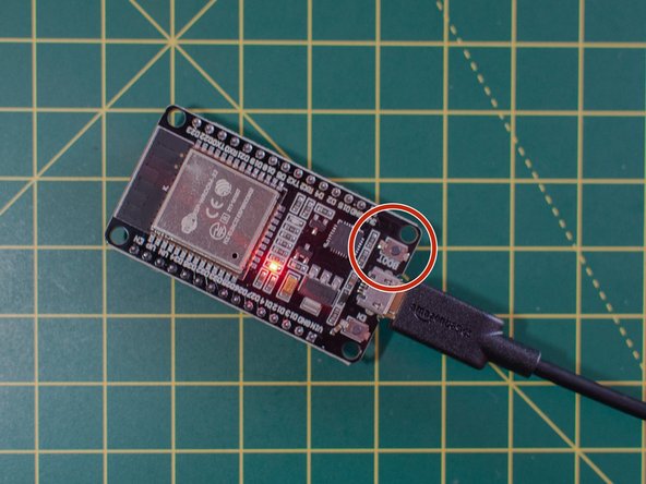
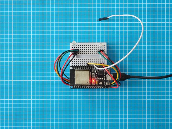
Plug your ESP32S board into your computer with the USB cable. You should see a red light on the board, which means it is powered up.
-
-
-
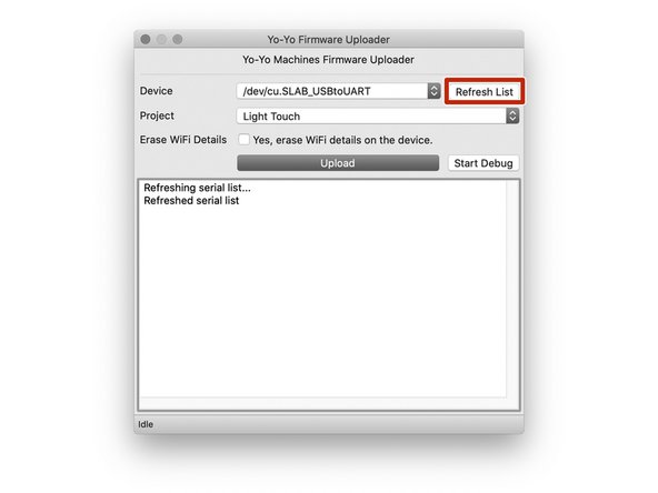
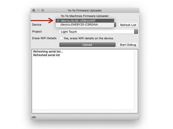
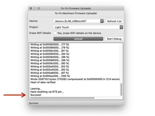
Open the Yo-Yo Firmware Uploader and select the device in the drop down menu. You may need to press “refresh list” if you do not see it in your list.
-
Your board's serial port should appear as '/dev/cu.SLAB_USBtoUART'
-
If the device doesn't appear, double check that your USB cable has a data line. Some USB cables only have power lines, as they are used for charging only.
-
Leave the 'Erase Wifi Details' box unticked.
-
-
-
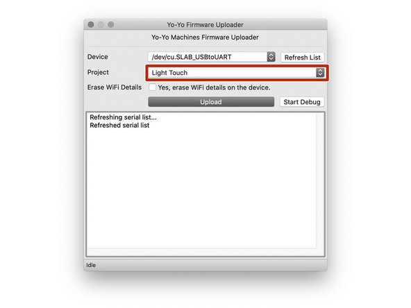
Use the 'project' drop-down menu to select which device you are making.
-
The image shows "Light Touch" as the selected project. Click on the menu to see other projects – we will be adding more periodically.
-
-
-
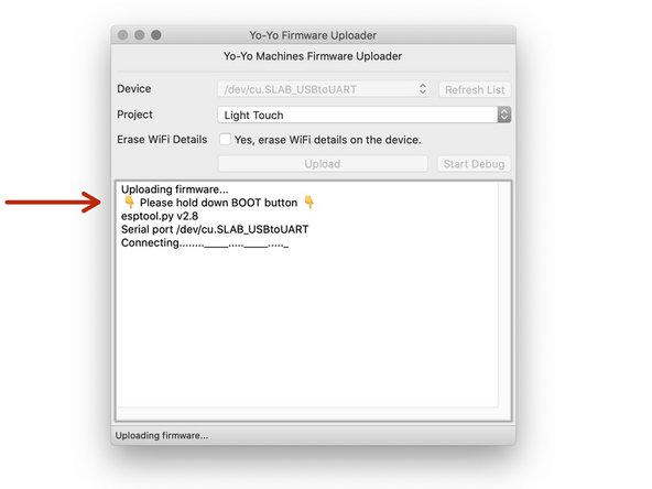
When you're ready, click on Upload to upload the latest firmware.
-
When prompted, hold the BOOT button on your board to set it to "programming mode". You can let go of the button once you see the text "Writing" in the console text.
-
If you receive an error, please make sure you have selected the correct device in the Firmware Uploader, and that you have pressed the 'BOOT' button as described above.
-
When the uploader finishes transferring the firmware to the device, it will say "Success!"
-
In the future, if you want to reset a device to factory settings, you can do so by ticking the "Erase WiFi Details" box and re-uploading the firmware.
-
-
-
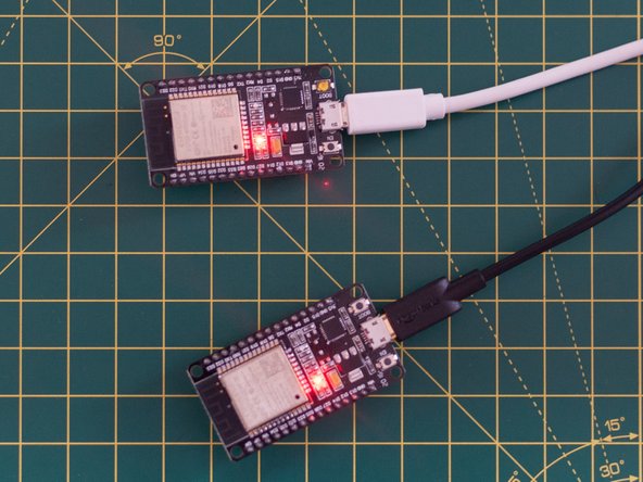
If you have another device to set up, you can repeat the previous step with the second ESP32S board.
-
Unplug the first device from your computer to make sure that you that you upload the firmware to the second device.
-
Select the device in the drop down menu of the Yo-Yo Firmware Uploader . You may need to press “refresh list” if you do not see it in your list.
-
-
-
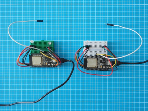
There are two main methods for setting up the network and pairing Yo–Yo Machines. In the first, both devices are set up in the same space, before one of them is sent to a remote location. In the second, devices are set up in separate spaces while coordinating with someone over the phone.
-
Both methods are covered in the following guide, but setting up a pair in the same space is shown as the primary method.
-
-
-
Power up the first ESP32S (with uploaded firmware) using a USB port or USB power supply and wait 10 seconds.
-
Now that the firmware is loaded, you can power your ESP32Ss from any USB power supply – there is no need to use a computer anymore.
-
If you are setting up two devices in the same space, turn on the second ESP32S at least 10 seconds after the first. If you are setting them up remotely, you do not need to synchronise in this way. You should still wait at least 10 seconds before proceeding so the ESP32Ss can establish a network.
-
With your mobile device or computer, connect to the newly created Wi-Fi network named “Yo-Yo-####” with the password “blinkblink”. If you are viewing these instruction online on our website, use another device to connect to the new network so you can keep the instruction open. This procedure is the same whichever method you are using.
-
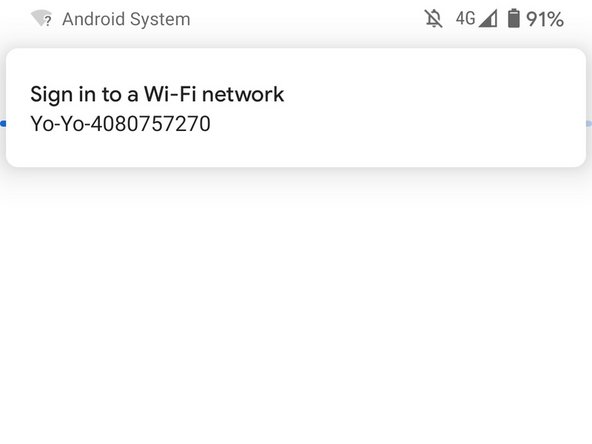
Android users may be prompted with a "Sign in to a Wi-Fi network" notification. Click this to open the captive portal (next).
-
-
-
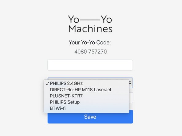
A captive portal should open automatically.
-
If the captive portal doesn't open on the device you are using, you may have to try with an alternative smartphone / tablet / laptop.
-
The captive portal will show the 5 Wi-Fi networks with the strongest signals. Sometimes you may not see the network that you would like to connect to, if this is the case, move your hardware closer to your router.
-
The ESP32S board cannot connect to Wi-Fi networks with names longer than 31 characters. If your Wi-Fi network's name is too long, then you will need to change it to a shorter name to complete the build.
-
-
-
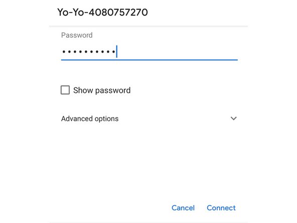
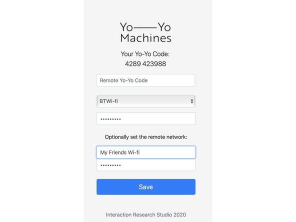
Fill in the prompts with credentials for the Wi-Fi network that you want to connect to.
-
When you are setting up two devices in the same space, you also have the option to include the Wi-Fi credentials of the network you want to send the device to. When you send the second device to someone, it will then automatically connect to their network.
-
Including the Wi-Fi credentials of the remote network when setting up a pair will store both the home and remote network credentials to both devices, so it will not matter which device you send away. For security purposes, the Wi-Fi credentials can never be retrieved from the devices later.
-
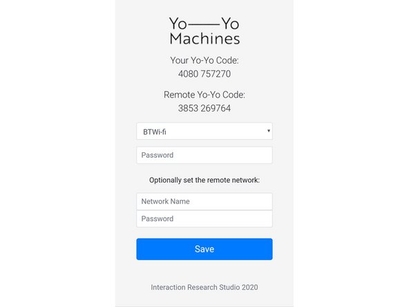
The image here shows two devices being set up in the same space. Note that the Yo-Yo codes have been exchanged automatically. Information on how to enter codes manually for remote setup is in the next step.
-
-
-
If you are setting up two devices in the same space, they have already exchanged Yo-Yo Codes automatically. Feel free to skip this step and press "Save"
-
Copy the text under the heading “Your Yo-Yo Code”.
-
Send your Yo–Yo Code to your partner via SMS, email, etc., in exchange for the one from their device.
-
Enter the Yo-Yo Codes for the partner devices in the text field named “Remote Yo-Yo Code”. It should be in the same format as yours eg: “4289 423988”. Once the forms are complete, press “Save”.
-
-
-
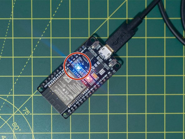
Wait for the devices' blue LEDs to blink 3 times to confirm the local wifi details are correct. If these details have been inputted incorrectly, please reconnect to the Yo-Yo-#### network and try again.
-
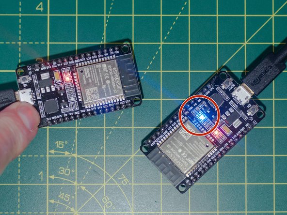
Once both devices have confirmed they can connect to their respective wifi networks, the connection between the devices can be tested. This is done by pressing the “BOOT” button of one device to blink the on-board led of the other.
-
-
-
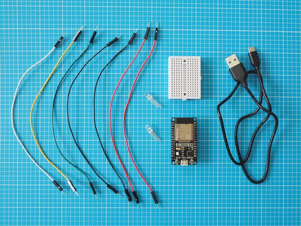
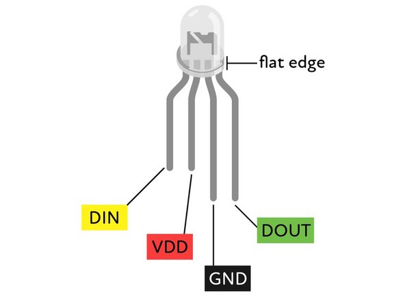
Gather your components and take a moment to identify them.
-
-
-
Orientation of the pins are signified by the lengths of the legs.
-
DIN = Data In
-
VDD = Supply voltage
-
GND = Ground
-
DOUT = Data Out
-
Some LEDs have leg lengths like the second image. If yours match this, please refer to this for wiring.
-
-
-
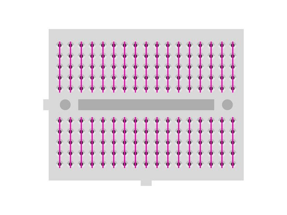
Bread boards are used to create quick connections between electronic components.
-
They have sockets that are electrically connected in rows. The connected sockets are shown as green lines in this diagram.
-
Jumper leads and components place in these rows will be connected together.
-
-
-
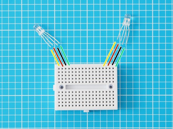
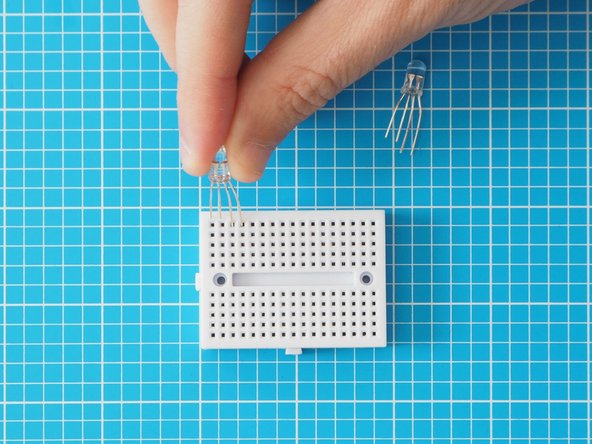
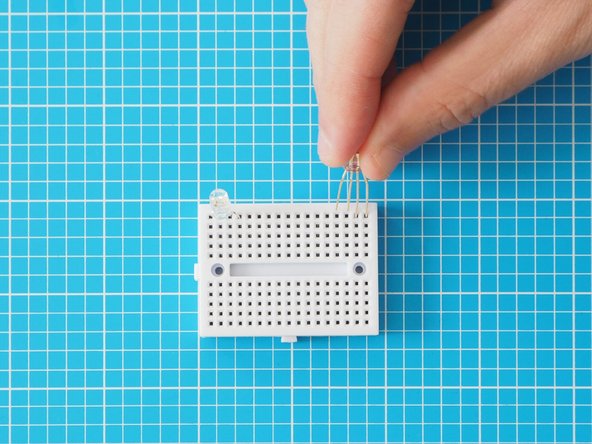
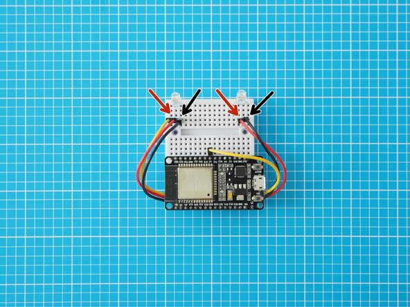
Place LEDs in breadboard as pictured. Make sure the orientation of the LEDs are the same (short legs to the left of the breadboard)
-
-
-
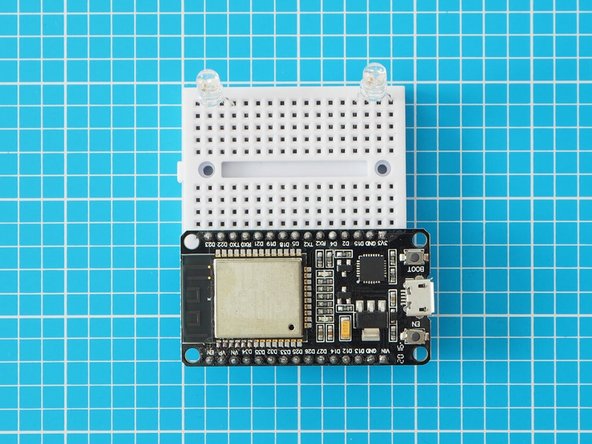
Place one side of the ESP32 onto the other side of the breadboard. The side used should be the same side as the button labelled boot.
-
Make sure all the pins are lined up and give the ESP32 a good solid push to plug it all the way into the breadboard.
-
-
-
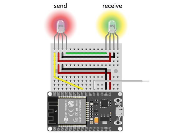
Wire the leftmost pin (DIN) of the LED to pin D5 of the ESP32.
-
Next, wire the adjacent two pins (VDD and GND) to the equivalent pins on the other LED.
-
-
-
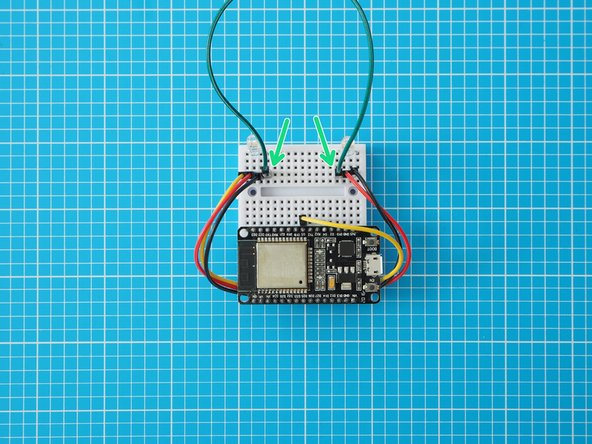
Connect the remaining leg (DOUT) of the lefthand LED to the leftmost leg (DIN) of the righthand LED
-
-
-
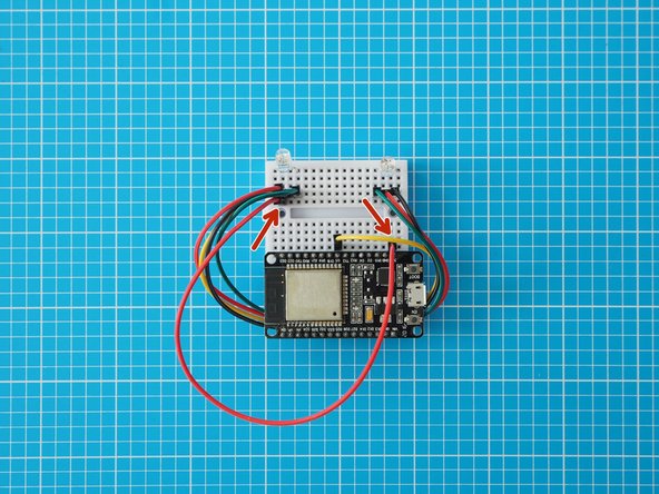
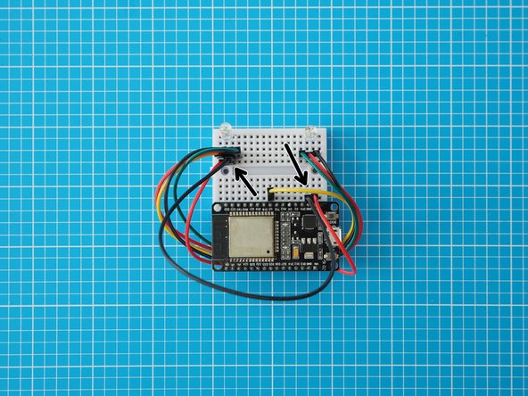
Add a wire in line with the LED's centre left leg (VDD) and connect that to the ESP32 3v3 pin. This LED leg is the shorter leg of the middle legs.
-
Add a wire in line with the LED's centre right leg (GND) and connect that to the ESP32 GND pin. This LED leg is the longer of the middle legs.
-
Please check your wiring and make sure you have connected this correctly. Wiring your LED backwards can damage it permanently.
-
the ESP32 has two GND pins. We recommend connecting to the one adjacent to the 3v3 pin for ease of use.
-
-
-
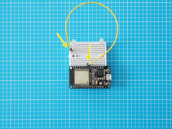
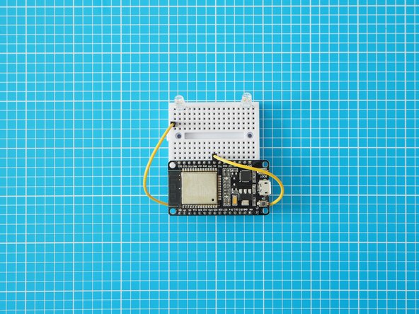
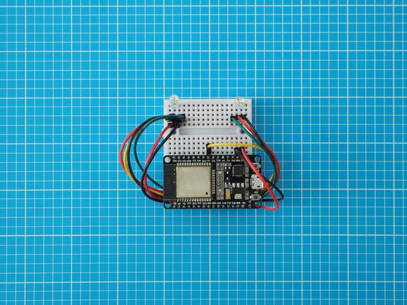
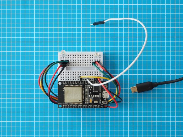
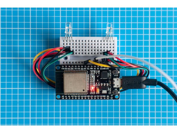
Add the final jumper wire in line with ESP32 pin D4.
-
-
-
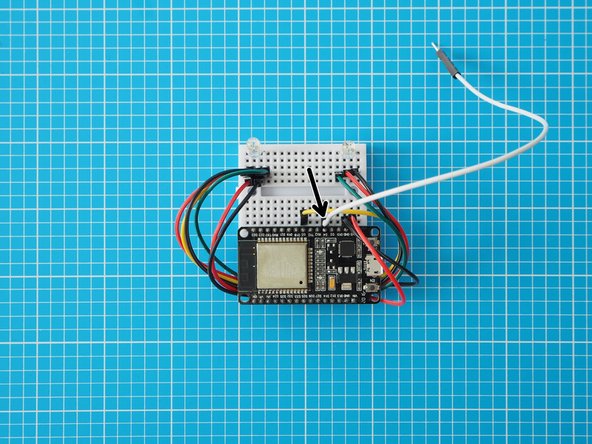
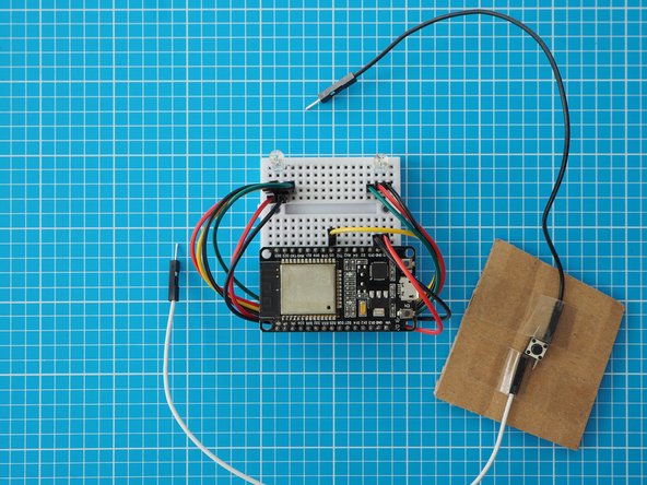
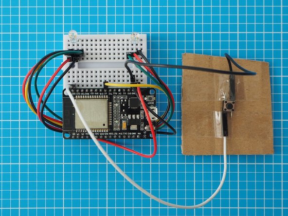
An external Button can be used instead of capacitive touch by adding a switch between pin D23 and GND on the ESP32.
-
-
-
Plug in your USB micro cable.
-
Make another Light Touch device using the same steps (11 - 21).
-
You can make both Light Touch devices in the same household and post one to your remote partner. Alternatively, they can be made remotely and paired via the internet.
-
Use the Network Setup guide to pair two Light Touch devices. We assume you'll do before you start assembling the electronics, but you can link or re-link them at any time.
-
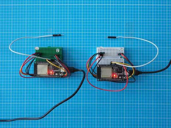
When you power up the devices the two addressable LEDs should blink as an indicator that you've wired up your LEDs correctly. Also the blue LED onboard the ESP32S board should blink to show the network connection is working.
-
-
-
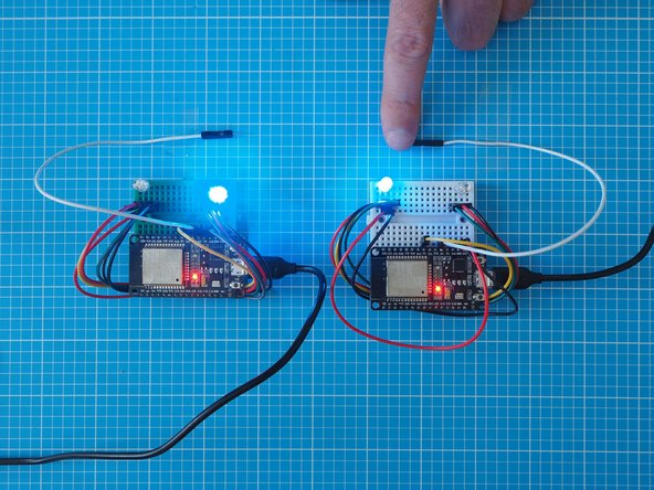
Press and hold the capacitive touch lead (white) on one Light Touch device to scroll through different colours. Let go to select a colour.
-
Tap quickly on the capacitive touch lead to send this colour to the other Light Touch Device.
-
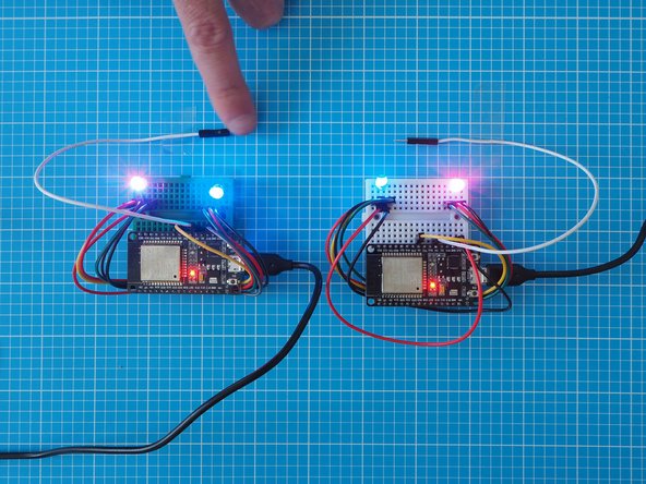
Using the second Light Touch, select and send a colour back.
-
-
-
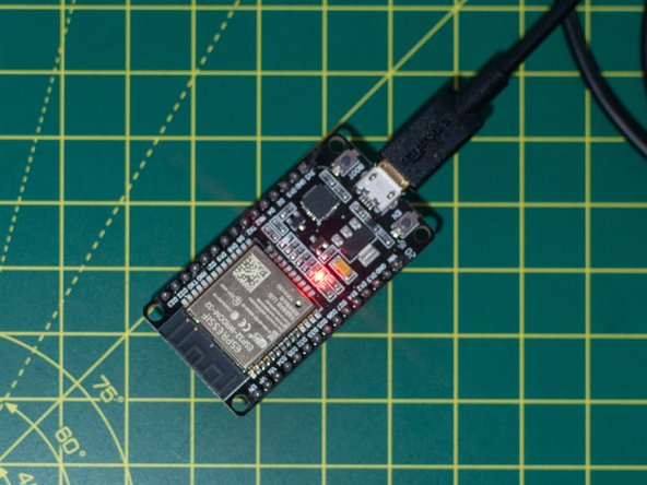
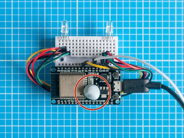
This step is optional, but the red power LED on the ESP32S board can seem quite bright in a darkened space and interfere with the main LED's. Covering this LED with a piece of Blu Tack or tape will eliminate the issue.
-
-
-
By default, the LED's are programmed to slowly fade to off over 6 hours from the last touch. However, the fade time can be adjusted by adding additional jumper leads.
-
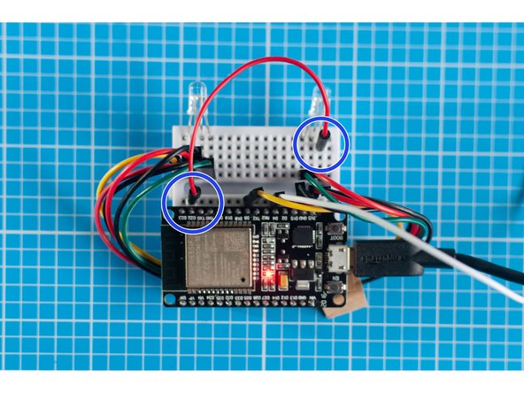
To reset the fade time to 3 hours from the last touch, to off, add a jumper lead between pin D22 on the ESP32S and ground (GND) as shown in the first picture.
-
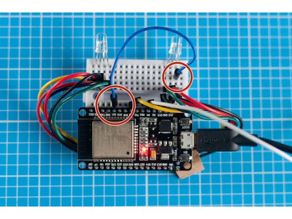
To reset the fade time to 1 hour from the last touch, to off, add a jumper lead between pin D21 on the ESP32S and ground (GND) as shown in the second picture.
-
To reset the fade time to 9 hours from the last touch to off, add jumper leads between pin D21 & D22 on the ESP32S and ground (GND).
-
These images show the leads connected to ground (GND) on the right LED but they could be connected to any ground (i.e. on the other LED or ESP32S) since they're all wired to one another.
-
-
-
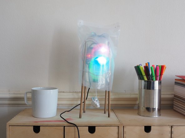
Now that your Light Touch device is working you can now think about what kind of enclosure you want to encase it in.
-
We have a few examples in the Enclosure section of the website , or feel free to invent your own.
-
-
-
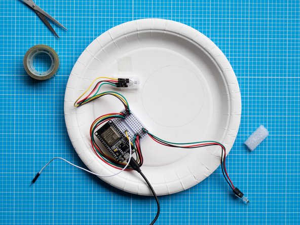
Gather the parts and tools shown in the picture.
-
-
-
Remove the LEDs from the breadboard.
-
Add male to female extension jumper wires to each of the legs of the LEDs and place them in their corresponding position in the breadboard.
-
Make sure you have correctly wired up the LEDs, especially checking that the centre 2 legs of each led are wired correctly to the breadboard.
-
Test the device to check that the circuit is working properly.
-
-
-
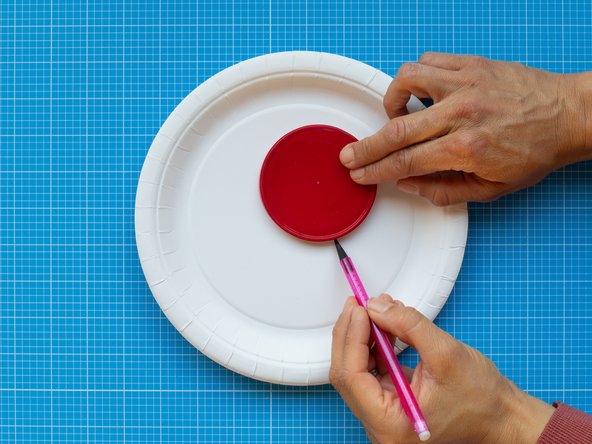
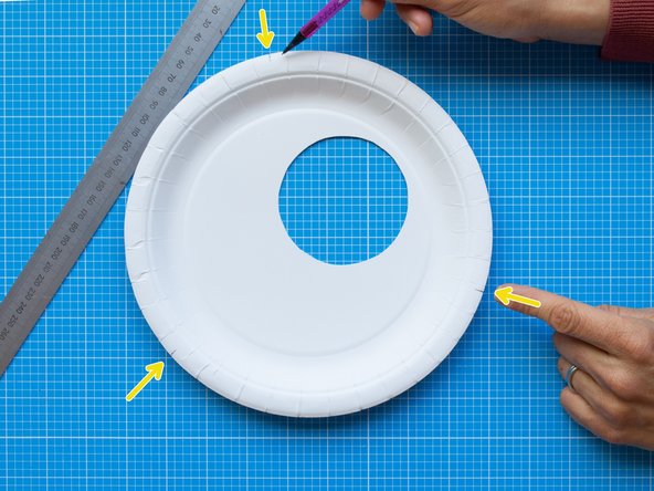
Mark a circular window of approximately 85 mm diameter in one plate. The circle should be located off centre to allow space for storing the electronics.
-
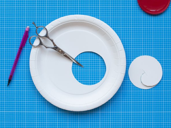
Cut the circle with scissors or a scalpel.
-
Mark three equidistant points along the edge of the plate. These points will be the guides for positioning the bulldog clips that will hold together the lamp.
-
The backside of the plate will be the front of your light.
-
-
-
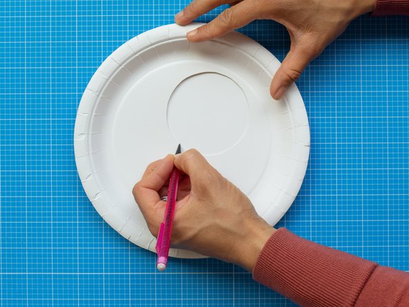
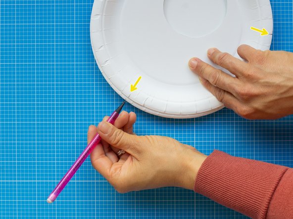
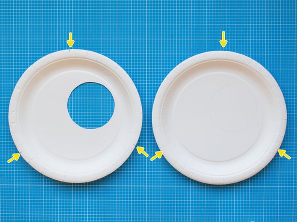
On a new plate, mark the area of the window by placing the cut plate on top. The marked circle will work as a white background for the LED lights of your device. This lighting area should remain clear. All the electronic components will be placed around it.
-
While in position, copy the three marks from the front plate. The marks will help you to align both plates together.
-
-
-
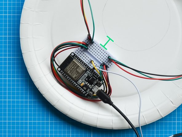
Fix the breadboard assembly around the lighting area as shown in the picture. The breadboard has a double sided tape backing which can be used to attach it to the plate.
-
Position the breadboard at least 1 cm away from the marked area so that it remains hidden once you close the device.
-
Make sure the breadboard cables are tucked under the board. The capacitive touch lead should be left aside.
-
-
-
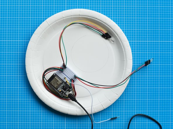
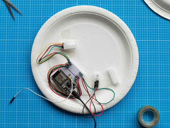
Position the LEDs around the lighting area following the picture as a guide. The LED to the upper left of this image is your 'send' light, the other is your 'receive' light.
-
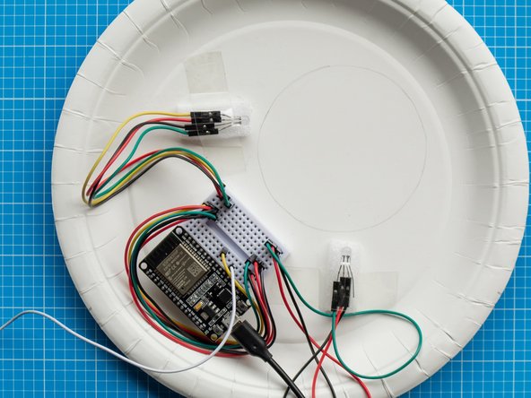
Once you have decided the right position of both lights, secure the LEDS to the plate with sellotape. Use two foam strips (from ESP32S board packaging) as spacers to elevate the LEDS from the plate.
-
For a better lighting effect avoid having the lights in front of each other.
-
The spacers help to create indirect lighting across the white circular area and their height can change the effect and tones of the light. You can play with the position of the LEDs while having the lights on to get the desired effect.
-
-
-
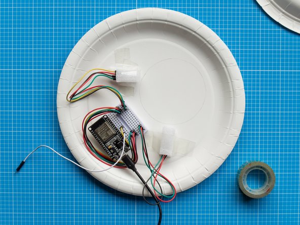
Place the two remainer foam strips on top of each LED and secure them with tape. These will act as a diffuser to the lights.
-
-
-
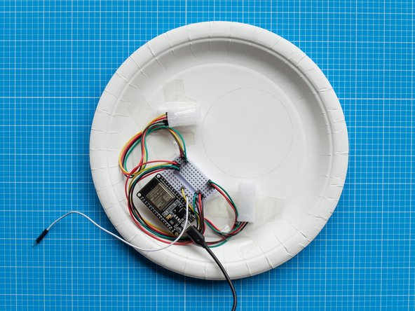
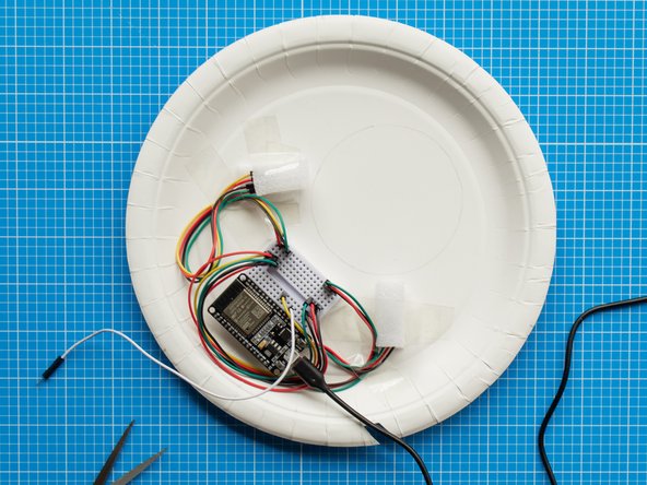
Now that the setup of the LEDs is complete, you can tidy up the cables by securing them to the plate with sellotape. This will help to have a tighter fit when you clip the front and back plate together.
-
Make sure to leave the capacitive touch lead aside.
-
-
-
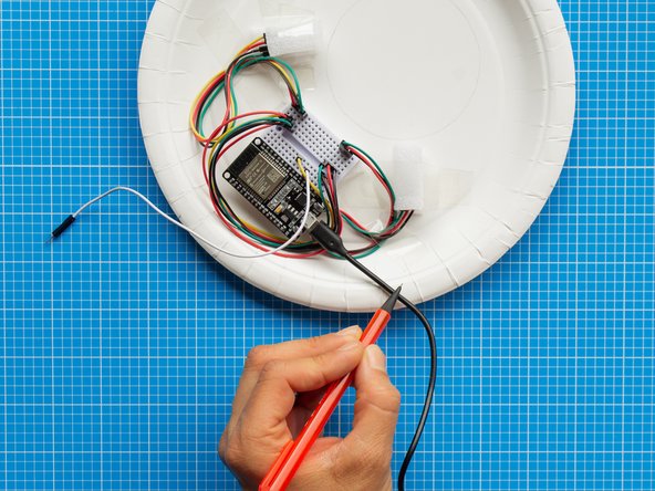
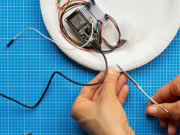
Now you will make an opening on the brim of the plate to let the micro USB lead out so that the front plate and back plate can close together tightly.
-
With a pencil, mark the outline of the USB lead where the cable touches the brim of the plate.
-
Make an opening in the shape of a slit with the help of scissors. The opening should be slightly wider than the cable.
-
-
-
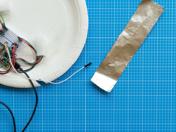
Cut a 4 x 18 cms strip of aluminium foil and fold it in half in both directions until it is about 2 x 9 cms.
-
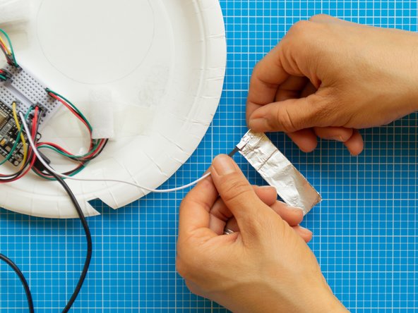
Take one end of the foil strip and wrap it around the pointy connector of the capacitive touch lead.
-
Wrap the connector a couple of times and press it tightly so that it is properly secured to the foil.
-
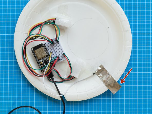
Place the wrapped connector on the plate so that the aluminium foil sticks outside the plate about 1 cm on the right bottom guide mark on the brim of the plate
-
Make sure the sticking foil matches the position of the guide mark as it will eventually be secured with the bulldog clip.
-
Once in position fix the connector and foil strip to the plate with sellotape.
-
-
-
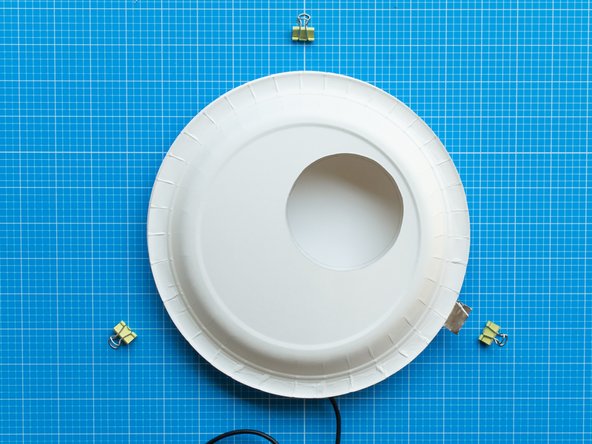
Place the front plate on top of the back plate. The electronics will be fully covered and the white lighting area in the circular window will be clear.
-
Make sure the guide marks in both plates are aligned.
-
Fold back the foil capacitive touch button so that it covers the brim of front plate.
-
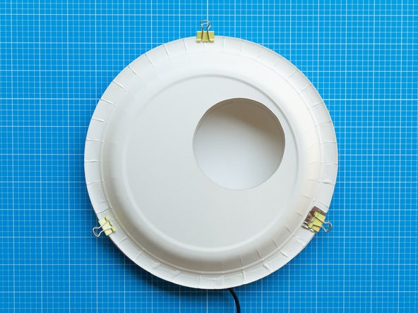
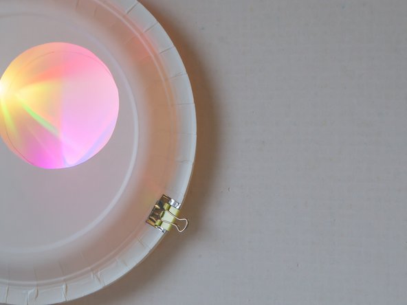
Once in position, secure both plates together with the three bulldog clips.
-
The bulldog clip that touches the foil will become the capacitive touch button, as the foil will transfer a signal whenever the clip is touched.
-
-
-
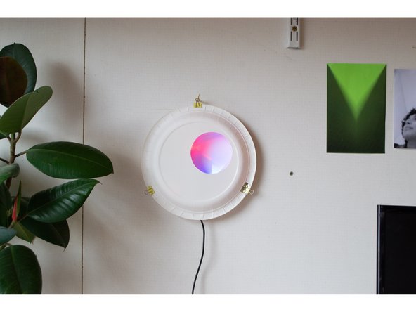
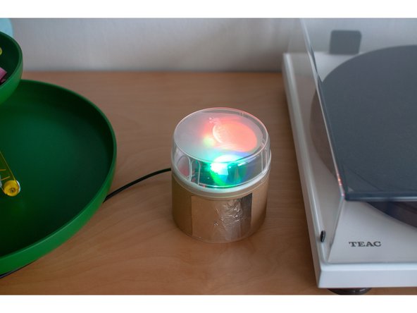
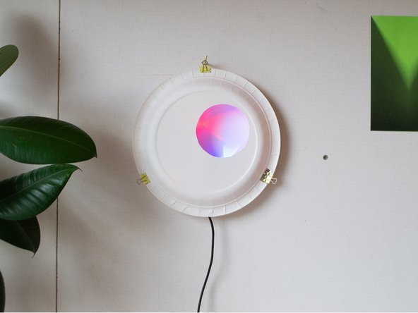
Light Touch is ready to use. You can place it on a wall by hanging it to an eye hook or nail from the top bulldog clip.
-
Choose locations for your device that are not too brightly lit. The LEDs are bright, but may seem washed out if near a sunny window.
-
Light Touch devices work best when plugged into dedicated adaptors like phone chargers. They do not run run well when plugged into laptops or computers as these will struggle to power the LEDs.
-
Enjoy!
-
-
-
Use the capacitive touch bulldog clip to operate the device.
-
Press and hold the bulldog clip to scroll through different colours. Let go to select a colour.
-
Tap quickly on the bulldog clip to send this colour to the your paired Light Touch device.
-
Receive a second colour back from your paired Light Touch device.
-
You can make and pair both Light Touch devices in the same household and post one to your remote partner. Alternatively, they can be made remotely and paired via the internet.
-
Use the Network Setup guide to pair two Light Touch devices. We assume you'll do before you start assembling the electronics, but you can link or re-link them at any time.
-